Highly Efficient Energy Transfer in SAE J2954 Standard
Inductive Charging (High Power / EV)
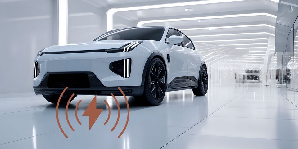
As part of a customer project, PACK LitzWire developed HF litz wires for an inductive charging system according to SAE J2954. The system operated at a nominal frequency of 85 kHz and was intended to safely transmit charging powers in the range of up to 11 kW. The coils were integrated into the underbody of the vehicle or into floor panels and were thus exposed to strong thermal, mechanical, and climatic loads.
The Challenge
The combination of high currents and an operating frequency of 85 kHz led to pronounced electromagnetic and thermal effects that had to be addressed in the project.
- Electromagnetics: Skin and proximity effects significantly increased the AC resistance of the windings.
- Thermals: In the potted charging pads, there was a risk of local hot spots and limited heat dissipation.
- Mechanics: Underbody integration required high robustness against vibrations, shock loads, and temperature cycles according to automotive standards.
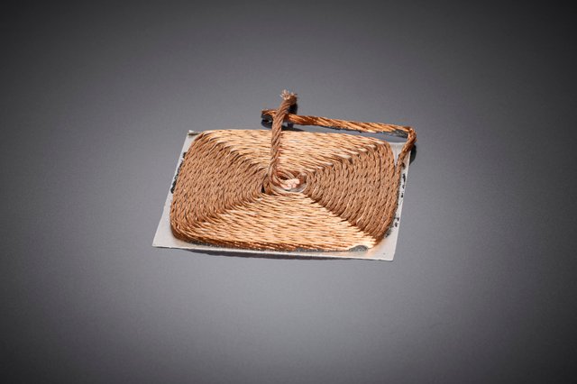
The HF coil designed for the inductive charging system forms the basis for low-loss energy transfer according to SAE J2954 and is designed for high charging power as well as robust underbody integration in the vehicle.
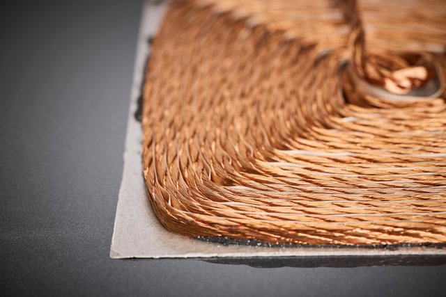
The optimized winding geometry of the HF litz wire ensures homogeneous current distribution, reduced AC losses, and stable thermal performance within encapsulated high-performance charging pads at 85 kHz.
Support from PACK LitzWire
PACK LitzWire worked closely with the customer to optimize the HF litz wire for these special requirements.
- AC Loss Analysis: Using simulation-based tools, skin and proximity losses of various litz wire constructions were calculated under realistic operating conditions.
- Litz Wire Optimization: Based on the simulations, PACK LitzWire defined the optimal single wire diameter, the appropriate stranding lay, and an efficient copper fill factor to minimize AC resistance at 85 kHz while ensuring mechanical stability.
- Documentation: Complete material data sheets and test reports were provided for customer-side validation according to SAE specifications.
Result
Thanks to the computer-aided preliminary design, several prototype iteration loops could be saved in the project. This resulted in a customized HF litz wire solution with homogeneous current distribution, reduced AC resistance, and stable thermal performance – reliably avoiding hot spots and fully meeting customer requirements.
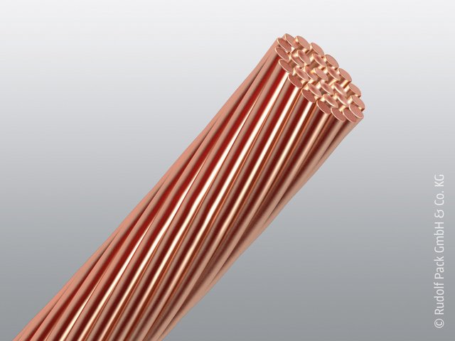
RUPALIT®
RUPALIT® is the classic among high-frequency litz wires for applications requiring maximum efficiency with minimal losses. With individual cross-sections and the highest single wire quality, we guarantee the reliability your components need in the long term.
Technical questions deserve precise answers.
Would you like to coordinate specifications or request a sample production? Our specialist departments will advise you directly – competently, bindingly, and reliably.

Product Manager

Internal sales team